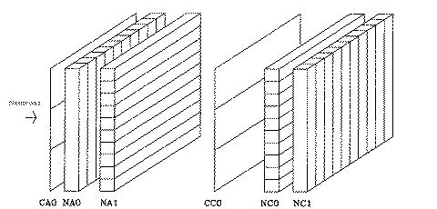

The INPOL (Indiana Neutron POLarization facility) zero degree polarimeter shown above consists of four planes of scintillator each consisting of 10 optically isolated cells oriented perpendicular to the incident flux of neutrons. Each of the cells has a photomultiplier tube at each end. The two front planes (NA0 and NA1) serve as the analyzer for the polarimeter and the back two planes (CA0 and CA1) as the catcher. The position of a hit in each plane is determined by which cell was hit and a timing difference in the signal to each end of that cell. The thin scintillator paddles (CC0 and CC1) are used to tag and veto charged particles. The relative timing and phototube gains are continuously monitored by tracking cosmic ray muons traversing the planes. Incident neutron energy is determined by time of flight to the first plane of the detector and neutron polarization is determined from the direction of scatter from front to back planes.
The detector was originally built and used in Los Alamos at the LAMPF/NTOF facility, but with the phasing out of nucleon physics at LAMPF and the closing of the polarized proton beam line it was moved (on loan) to IUCF where it replaced an older neutron polarimeter. It is currently housed on the zero degree beam line at 160 meters from the target.
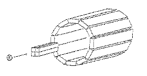
 In conjunction with the INPOL polarimeter the facility includes the Kent State polarimeter (shown to the right) on the 24 degree line, giving the capability of taking data at two angles at once.
The design is quite different with four small bars of scintillator serving as the analyzer and behind those a barrel-shaped catcher.
For more details on this polarimeter go to the Center for Nuclear Research at the KSU Physics Department.
(Includes a nicer picture.)

The first job of the INPOL electronics is to determine the type and validity of an event in the detector (i.e. valid neutron coincidence, cosmic ray, etc..). If an event is found to be valid in the hardware all the time and pulse-height signals from the phototubes are fed to FERA TDCs and ADCs. A FERA driver reads these modules via a front bus, and from the FERA driver the data stream, along with various data bits such as spin information, is sent directly to a VME crate using a Motorola MC68040 microprocessor, bypassing the typical CAMAC buffer. The VME system trasmits the CAMAC data via standard TCP/IP protocol on Ethernet to the host computer, a VAX station 4000-90, which is running IUCF's standard in-house data acquisition/replay software XSYS.
For a more detailed description of the electronics go to the INPOL project page at IUCF.

The building in which the neutron polarimeter is housed is fixed at a flight path of 160 meters. Formerly, the detector had been mounted in a movable trailer so the flight path could be adjusted to meet resolution requirements in a given experiment, but when the equipment was moved to IUCF this was not feasible.
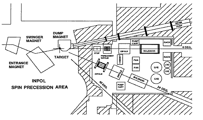
The target area is shown below:

Upstream of the target is a set af swinger magnets which are used to change the angle of incidence of the proton beam on the target between 0 and 24 degrees. When used along with the 24 degree beam line this gives us the capability to measure momentum transfers up to 2.3 fm^-1 at 200 MeV. Downstream of the target are a set of dipole magenets and a set of superconducting solenoids which are used to precess the spin of the outgoing neutrons to a state which is measureable in our polarimeter.
The proton beam is provided by HIPIOS (High Intensity Polarized IOn Source) which can give us 300 nA of about 70% polarized beam with pulses every 360 ns. The cyclotron is capable of accelerating the proton beam to 200 MeV and another set of superconducting solenoids just downstream of the cyclotron will precess the proton polarization to any of the three spatial orientations.
 Back to Nuclear Charge Exchange Homepage.

 )
)